Board Warp – A Technical Article
Pillarhouse International, in partnership with the Selective Soldering Academy, has produced a Technical Paper on Board Warp, Sag, Twist and Arch – What Is It, What Causes It and How Can It Be Overcome in The Selective Soldering Process?
Board Warp, Sag, Twist and Arch – What Is It, What Causes It and How Can It Be Overcome in The Selective Soldering Process?
What are Board Warp, Arch, Twist and Sag?
Board warping is the unintended change in the geometry of a Printed Circuit Board (PCB). Board warpage is the general term used to describe an altered PCB shape, regardless of the shape itself (bow, twist etc.). One of the primary challenges of processing a warped board is that the transition may take place as part of the soldering cycle. Therefore, the prior shape may not directly correlate to the shape of the PCB at the time of soldering.
Typical PCB Deformation Shapes
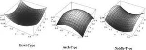
Root Causes:
Board Design: Unbalanced Layers/Misaligned Fibres
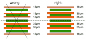
- In multilayer boards, distributing copper area and weight equally about the theoretical centreline (the ‘neutral axis’) minimizes warp
- Bow and Twist effect is normally the result of fibre layers not being perpendicular to one another.
Thermal Expansion/Heat
- Most common PCBs are based on a laminate of multiple layers of weaved glass fibre cloth and epoxy. These laminates have so-called viscoelastic material properties. This means that properties such as elasticity and thermal expansion drastically change above a certain temperature, called the glass transition temperature (Tg). When soldering the PCB assembly, the laminate will be exposed to temperatures above the glass transition temperature. Even though the epoxy will try to expand in all directions, mechanical devices (Plate Through Hole (PTH) and via) act as reinforcements and work to restrict the even expansion. The result can be some degree of wave, sag or bow.
Component Weight, Shields or Heat Sinks
- Components may directly affect the flatness of the PCB. If the PCB contains heavy heat sinks, the thermal properties of the heat sinks would result in cooler areas and limit expansion locally. Physically heavy components or board features could serve to apply weight directly to the weakest areas (typically an unsupported centre) and would cause sag during the transition phase. Shielding or any mechanical device that would serve to limit movement of the board could result in uneven expansion and therefore a negative change in co-planarity.
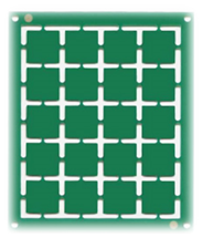
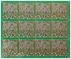
Examples of Designs Features Likely To Warp:

Overcoming Board Warpage
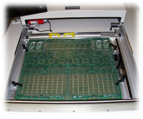
The old standard for warp mitigation is to use a pallet or fixture. The advantage is the board is held on four edges, so it is supported on all sides. The use of pallets also facilitates mechanical features to support the board in areas of weakness. The major issues with using pallets are added cost and reduced flexibility in a high mix environment.
The most common currently used machine feature, to mitigate warpage, is side clamping both in a horizontal and vertical plane. The functionality of such systems is limited due to the fact that the board in most cases is only held and clamped on 3mm of two edges (not four).
Effective Solution for Board Warpage Correction
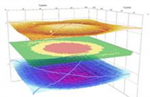
The actual shape of the PCB change is not repeatable in most cases. Predominantly, the board changes occur during preheat cycles but also as part of the selective soldering process due to the localized heating required to solder specific components. To adequately deal with these factors it is necessary to use a closed loop real time detection and correction system. Mapping of the board topography prior to any of the heat cycles yields inconsistent results.
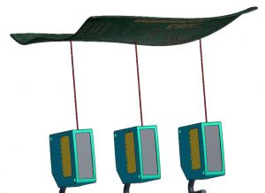
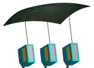
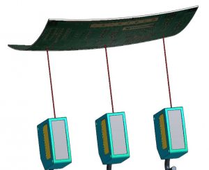
With the addition of a few monitoring points, the Pillarhouse system can measure any change in the board height (XY and theta already corrected with fiducial) and adjust accordingly. All it takes is to check a box next to any joint that needs correction and the machine automatically connects the warpage point to the joint in the program library. The system has the ability to follow complex contours that are completely different in direction and shape from one board to the next.
The complete article can be downloaded from this link here.
